
John Deere柴油機連桿與活塞銷/活塞環(huán)的裝配與標準值參數(shù)
詳細描述
John Deere約翰迪爾強鹿柴油機連桿與活塞銷、活塞環(huán)的裝配與標準值參數(shù)
IMPORTANT: There are different manufacturers/part numbers for piston and liner sets. These sets are not interchangeable. DO
NOT intermix piston/liner sets on the same engine. Check parts catalog for correct applications.
IMPORTANT: If a new piston and liner assembly is to be installed, DO NOT remove piston from liner. Push piston out of liner bottom only far enough to install piston pin.
1. Lubricate piston pin and bushing with clean engine oil.
IMPORTANT: Pistons must be installed on connecting rods from which they were removed, and new piston pin snap rings must be used. Piston and connecting rod must be assembled so combustion bowl in piston is offset toward fuel injection pump side of engine when long side of connecting rod is toward the camshaft side of engine.
NOTE: Some pistons are marked with an arrow on top of piston. Arrow must point to side marked “FRONT” on connecting rod when assembled.
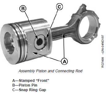
2. Assemble pistons and connecting rods, making sure the word “FRONT” (A) on side of piston and side of connecting rod are facing same direction.
3. Insert piston pin (B) into piston pin bore. NOTE: Some piston pin snap rings have sharp edges on both sides. These rings are reversible.
4. Install NEW piston pin snap rings with ring gap (C) facing down to the 6 o’clock position at bottom of piston (viewed from rod end) and sharp edge of ring facing away from piston pin. Make sure snap rings are seated in grooves of piston pin bore.

活塞環(huán)的安裝方法
IMPORTANT: Piston rings can be damaged if
expanded too far. Expand piston rings
only as far as necessary to install rings
on piston.
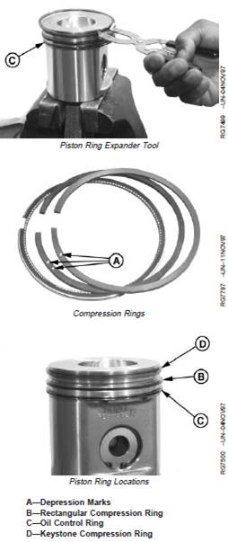
1. When installing new piston rings, use JDE85, JDE135,or KJD10140 Piston Ring Expander. Install oil ringexpander in bottom ring groove. Position end gaptoward either side of piston pin.
2. Install oil control ring (C) in bottom ring groove overring expander. Install with end gap on opposite side ofpiston from ring expander gap.
NOTE: Identify ring top as follows:If ring has no marks, it can be installed with eitherside facing top.If rings are marked with depression (“pip”), markshould be on top as shown (A). Ring with twodepression marks goes in the second groove.If ring is marked with paint strip, hold ring withgap facing you and turn ring so that paint strip isto the left side of gap.
3. Identify top side of compression rings. Top side ofrectangular and keystone compression rings will beidentified by marks on the top side of two rings.
4. Install rectangular compression ring (B) in center ringgroove with top of ring toward top of piston.
5. Position gap in rectangular compression ring onopposite side of piston from oil control ring (C) gap.
6. Install keystone compression ring (D) in top ring groovewith top of ring toward top of piston.
7. Position gap in keystone compression ring on oppositeside of piston from rectangular compression ring gap.

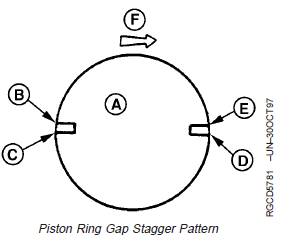
8. Stagger ring gaps on pistons as shown.
9. Coat pistons, liners and inside of JDE84 Piston RingCompressor with clean engine oil.
A—Piston Head
B—Top Compression Ring
C—Oil Control Ring Gap
D—Expander Ring Gap
E—Bottom Compression Ring Gap
F—Front of Engine

400-100-8969???15088860848
0574-26871589? 15267810868
0574-26886646? 15706865167
0574-26871569 18658287286


 Deutsch
 Espaol
 Franais
 Italiano
 Português
 日本
日本 韓國
韓國 阿拉伯
阿拉伯 български
 hrvatski
 esky
esky Dansk
Dansk Nederlands
 suomi
suomi Ελληνικ
 印度
印度 norsk
norsk Polski
 Roman
Roman русский
 Svenska
 中文(簡)
中文(簡)