
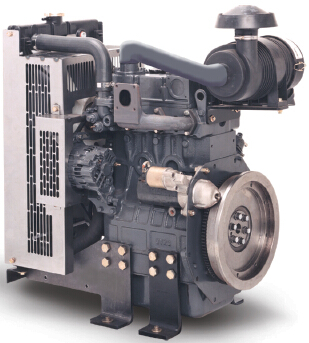
Perkins珀金斯100用戶手冊(cè)(英文)
詳細(xì)描述
Perkins 100 Series
Models KN, KL, KD, KH, KE, KF, KR and KS
USER’S HANDBOOK
2, 3 and 4 cylinder naturally aspirated diesel engines for
industrial, construction and agricultural applications
Publication TPD 1378E, Issue 2.
© Proprietary information of Perkins, all rights reserved.
The information is correct at the time of print.
Published in March 2002 by Technical Publications.
1
This document has been printed from SPI². Not for Resale
![]()
![]()
100 Series
Contents
Safety precautions ... ... ... ... ... ... ... ... ... ... ... ... ... ... ... ... ... ... ... ... ... ... ... ... ... ... ... . 3
General data ... ... ... ... ... ... ... ... ... ... ... ... ... ... ... ... ... ... ... ... ... ... ... ... ... ... ... ... ... . 4
Engine data . ... ... ... ... ... ... ... ... ... ... ... ... ... ... ... ... ... ... ... ... ... ... ... ... ... ... ... ... ... . 5
Location of engine parts .. ... ... ... ... ... ... ... ... ... ... ... ... ... ... ... ... ... ... ... ... ... ... ... ... . 6
Preventive maintenance .. ... ... ... ... ... ... ... ... ... ... ... ... ... ... ... ... ... ... ... ... ... ... ... ... . 8
2
User’s Handbook, TPD 1378E, issue 2
This document has been printed from SPI². Not for Resale
![]()
![]()
100 Series
Safety precautions
These safety precautions are important. You must refer also to the local regulations in the country of use.
Some items only apply to specific applications.
l Do not use these engines in marine applications.
l Do not change the specification of the engine.
l Do not smoke when you put fuel in the tank. Clean away fuel, which has been spilt. Material, which has
been contaminated by fuel, must be moved to a safe place.
l Do not clean, add lubricating oil, put fuel in the tank or adjust the engine while it runs.
l Do not make adjustments that you do not understand.
l Ensure that the engine does not run in a location where it can cause a concentration of toxic emissions.
l Other persons must be kept at a safe distance while the engine or auxiliary equipment is in operation.
l Do not permit loose clothing or long hair near moving parts.
l Keep away from moving parts during engine operation.
Warning! Some moving parts cannot be seen clearly while the engine runs.
l Do not operate the engine if a safety guard has been removed.
l Do not remove the filler cap or any component of the cooling system while the engine is hot and while the
coolant is under pressure, because dangerous hot coolant can be discharged.
l Do not use salt water or any other coolant which can cause corrosion in the closed cooling unit.
l Do not allow sparks or fire near the batteries (especially when the batteries are on charge) because the
gases from the electrolyte are highly flammable. The battery fluid is dangerous to the skin and especially
to the eyes.
l Disconnect the battery terminals before a repair is made to the electrical system.
l Only one person must control the engine.
l Ensure that the engine is operated only from the control panel or from the operators position.
l If your skin comes into contact with high-pressure fuel, obtain medical assistance immediately.
l Diesel fuel and lubricating oil (especially used lubricating oil) can damage the skin of certain persons.
Protect your hands with gloves or a special solution to protect the skin.
l Do not wear clothing which, is contaminated by lubricating oil. Do not put material, which is contaminated
with oil into the pockets of clothing.
l Discard used lubricating oil in accordance with local regulations to prevent contamination.
l Ensure that the control lever of the transmission drive is in the "out-of-drive" position before the engine is
started.
l The combustible material of some components of the engine (for example some seals) can become
extremely dangerous if it is burned. Never allow this burnt material to come into contact with the skin or with
the eyes.
l Use extreme care if emergency repairs must be made in adverse conditions.
l Do not allow compressed air to contact your skin. If compressed air enters your skin, obtain medical help
immediately.
l Fit only genuine Perkins parts.
CALIFORNIA Proposition 65 Warning
Diesel engine exhaust and some of it constituents are known to the state of California to cause cancer, birth
defects, and other reproductive harm.
User’s Handbook, TPD 1378E, issue 2
3
This document has been printed from SPI². Not for Resale
![]()
![]()
100 Series
General data
Read this section carefully before the engine is started
To start the engine
Caution: Ether starting fluids must not be used with these engines.
1 Move the throttle lever to the full-speed position.
2 Turn the start key anticlockwise to ’’HEAT’’ and hold it there for 20 to 30 seconds (maximum 60 seconds)
until the glow signal illuminates red.
3 With the signal illuminating red, turn the key clockwise all the way to ’’START’’, and crank the engine for 20
seconds maximum.
4 When the engine starts, release the key, which will spring back to ’’ON’’.
5 Turn the throttle lever down slowly to allow the engine to idle.
Note: If the glow signal illuminates rapidly for 2 to 3 seconds, or does not illuminate within 20 to 30 seconds,
this indicates a malfunction of the cold start system.
6 Turn the start key to the "OFF" position to stop the engine.
Venting the fuel system
1 Identify the location of the fuel lift pump.
2 Locate the vent screw on the fuel filter, and loosen off.
3 Operate the hand primer on the lift pump until air free fuel flows. Tighten vent screw.
4 Identify the vent screw on the fuel injection pump, loosen off, and operate the hand primer until air free fuel
flows. Tighten the vent screw.
5 Identify the fuel pipes from fuel injection pump to atomiser and loosen all off at the atomiser end. Turn the
engine on the starter motor until fuel flows from injector pipe. Tighten all pipes.
6 The engine is now ready to start.
Caution: When turning the engine on the starter do not exceed continuous rotation for more than 15 second
periods. Wait for 30 seconds between periods of turning if fuel does not flow on initial rotation.
Antifreeze
The anti-freeze mixture must consist of equal quantities of anti-freeze and water. The corrosion inhibitor in the
anti-freeze will be diluted if a concentration of less than 50% of anti-freeze is used.
Concentrations of more than 50% of anti-freeze may have an adverse effect on the performance of the coolant.
Caution: Do not use salt water or any other coolant that can cause corrosion in the closed cooling circuit.
Altitude
Contact the Perkins Applications Department for information on the effect of ambient conditions on the Perkins
100 Series engines.
Adjustment of the engine speed range
The idle or maximum speed setting must not be changed by the engine operator because this can damage the
engine or the transmission. The warranty of the engine can be affected if the seals on the controls of the fuel
injection equipment are broken during the warranty period by a person who is not approved by Perkins.
4
User’s Handbook, TPD 1378E, issue 2
This document has been printed from SPI². Not for Resale
![]()
![]()
100 Series
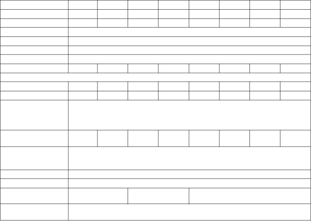
Engine data
Engine type
Engine code
102-05
KN
103-07
103-10
KD
103-11
KS
103-13
KH
103-15
KE
104-19
104-22
KR
KL
3
KF
4
Number of cylinders
Cylinder arrangement
Cycle
2
3
3
3
3
4
In-line
Four stroke
Naturally aspirated
IDI special swirl
Induction system
Combustion system
Cubic capacity (litres)
0,451
0,676
0,954
1,131
1,330
1,496
1,995
2,216
Capacity of industrial oil sump and filter (litres)
Maximum
Minimum
1,9
1,3
2,8
2,1
3,5
2,7
4,9
3,7
5,7
4,5
5,7
4,5
7,1
5,3
8,2
6,3
Use only good quality lubricating oil which meets (and not exceeds) any of the
Lubricating oil
specification
specifications listed:
API CC/CD/CE/CF/CF-4/CG-4
ACEA E1/E2/E3
Coolant system capacity
- engine only (litres)
0,98
1,25
1,70
1,90
2,50
2,65
3,3
3,6
Clean soft water with 50% Anti-freeze concentration ethanediol base/ethylene glycol,
corrosion inhibitor to BS 6850: 1985 or ASTMD 3306-74 or AS 2108-1977
See "Antifreeze" on page 4
Coolant specification
Diesel fuel specification
Direction of rotation
Minimum cetane number 45 (Aviation fuel JP4 must not be used)
Clockwise view from the front
Cylinder head torques
Kgf m (lbf ft)
3,5 - 4,0
(25 - 29)
5,0 - 5,3
(36 - 38)
9,9 - 10,5
(72 - 76)
Tappet settings cold
inlet / exhaust
0,2 mm
(0.0078 in)
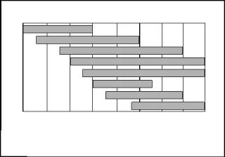
Recommended viscosity grades
0W
5W20
10W30
15W40
20W50
20
30
40
-30
-22
-20
-4
-10
14 32
0
10
50
20
68
30
86 104 122 F
40
50
o
o
C
Ambient temperature
A
Always ensure that the correct viscosity grade of lubricating oil is used for the ambient temperature range in
which the engine will run, as shown in the above chart.
User’s Handbook, TPD 1378E, issue 2
5
This document has been printed from SPI². Not for Resale
![]()
![]()
![]()
100 Series
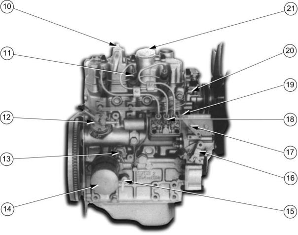
Location of engine parts
Introduction
Perkins engines are built for specific applications and the views that follow do not necessarily match your
engines specification.
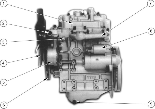
Left side
1 Induction manifold.
2 Water outlet.
3 Water temperature switch.
4 Fan, mounted on water pump.
5 Alternator.
6 Crankshaft pulley.
7 Exhaust manifold.
8 Starter motor.
9 Lubricating oil drain plug.
6
User’s Handbook, TPD 1378E, issue 2
This document has been printed from SPI². Not for Resale
![]()
![]()
100 Series
Right side
10 Open engine breather.
11 Atomiser.
12 Fuel lift pump.
13 Coolant drain plug.
14 Lubricating oil filter.
15 Lubricating oil dipstick.
16 Throttle lever.
17 Mechanical stop control (electrical stop control at rear of pump).
18 Fuel injection pump.
19 Position of engine number label.
20 Oil pressure switch.
21 Filler cap for lubricating oil.
User’s Handbook, TPD 1378E, issue 2
7
This document has been printed from SPI². Not for Resale
![]()
![]()
100 Series
Preventive maintenance
Preventive maintenance periods
The preventive maintenance periods in the schedules below apply to average conditions of operation. Check
the periods given by the manufacturer of the equipment in which the engine is installed. Use the periods that
are shortest. When the operation of the engine must conform to the local regulations these periods and
procedures may need to be adapted to ensure correct operation of the engine.
It is good preventive maintenance to check for leakage and loose fasteners at each service.
These maintenance periods only apply to engines that are operated with fuels and lubricating oils that conform
to the specifications given in this handbook.
Schedules
The schedules, that follow, must be applied at the interval (hours or months) that occur first.
A
B
C
Every day or every 8 hours
First service (20 / 50 hours)
Every 100 hours or 3 months
D
E
F
Every 200 hours or 6 months
Every 400 hours or 12 months
Every 600 hours or 18 months
A
B
C
D
E
F
Operation
l l l l l
l
Check the coolant level (top up with coolant only)
Check the concentration of the coolant
l Renew the coolant (fill slowly, ensure correct quantity is used)
l
l l l Check the level of the engine lubricating oil
l l l l l Renew the engine lubricating oil (fill slowly, ensure correct quantity is used)
l l l l l Renew the engine oil filter
l l l l l Drain water from the fuel filter and pre-filter
l l l Renew the fuel filter canister (N.B. Airvent screws on filter and fuel pump)
l l l l l l Check tension of the alternator drive belt
l
Check the alternator drive belt for wear
l Renew the alternator drive belt
Check and adjust idle speed
l
l
l Tighten the cylinder head
l Check and adjust valve clearances
l Check electrical systems
l Check all nuts and bolts for tightness
Check the injectors for performance
l Clean the air filter (earlier check may be necessary)
Renew the air filter element
l
l
l l l
l l l l l l Check and correct any leaks or engine damage
Note: All operations to be carried out by trained personnel with reference to the Workshop Manual where
necessary.
8
User’s Handbook, TPD 1378E, issue 2
This document has been printed from SPI². Not for Resale
![]()
![]()

400-100-8969???15088860848
0574-26871589? 15267810868
0574-26886646? 15706865167
0574-26871569 18658287286


 Deutsch
 Espaol
 Franais
 Italiano
 Português
 日本
日本 韓國
韓國 阿拉伯
阿拉伯 български
 hrvatski
 esky
esky Dansk
Dansk Nederlands
 suomi
suomi Ελληνικ
 印度
印度 norsk
norsk Polski
 Roman
Roman русский
 Svenska
 中文(簡(jiǎn))